
Liquid Cooling Connectors
Liquid Cooling Connector Helium Leak Detection System
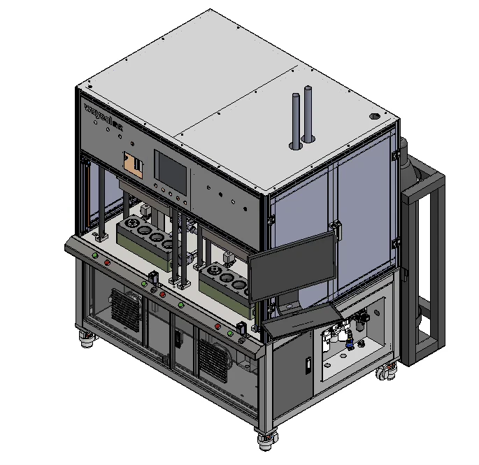
A dry helium leak testing system for male connectors, female connectors, and complete liquid cooling connector assemblies. After manual loading, the PLC controls automatic sealing, pressure-hold gross leak testing, evacuation, helium filling, fine leak testing, and helium recovery. Two chambers operate alternately or independently.
SKU Details
Key Configuration
Use these details as a starting point. Chamber dimensions, tooling, pumping speed, and automation level can be configured around the actual component and cycle time.
Technical Specifications
| Test method | Pressure-hold gross leak check + vacuum chamber helium mass spectrometer fine leak test |
|---|---|
| Workpiece leak rate criterion | 1.0 × 10⁻⁶ Pa·m³/s |
| Vacuum chambers | 2 split chambers with mating halves; alternating operation or independent use |
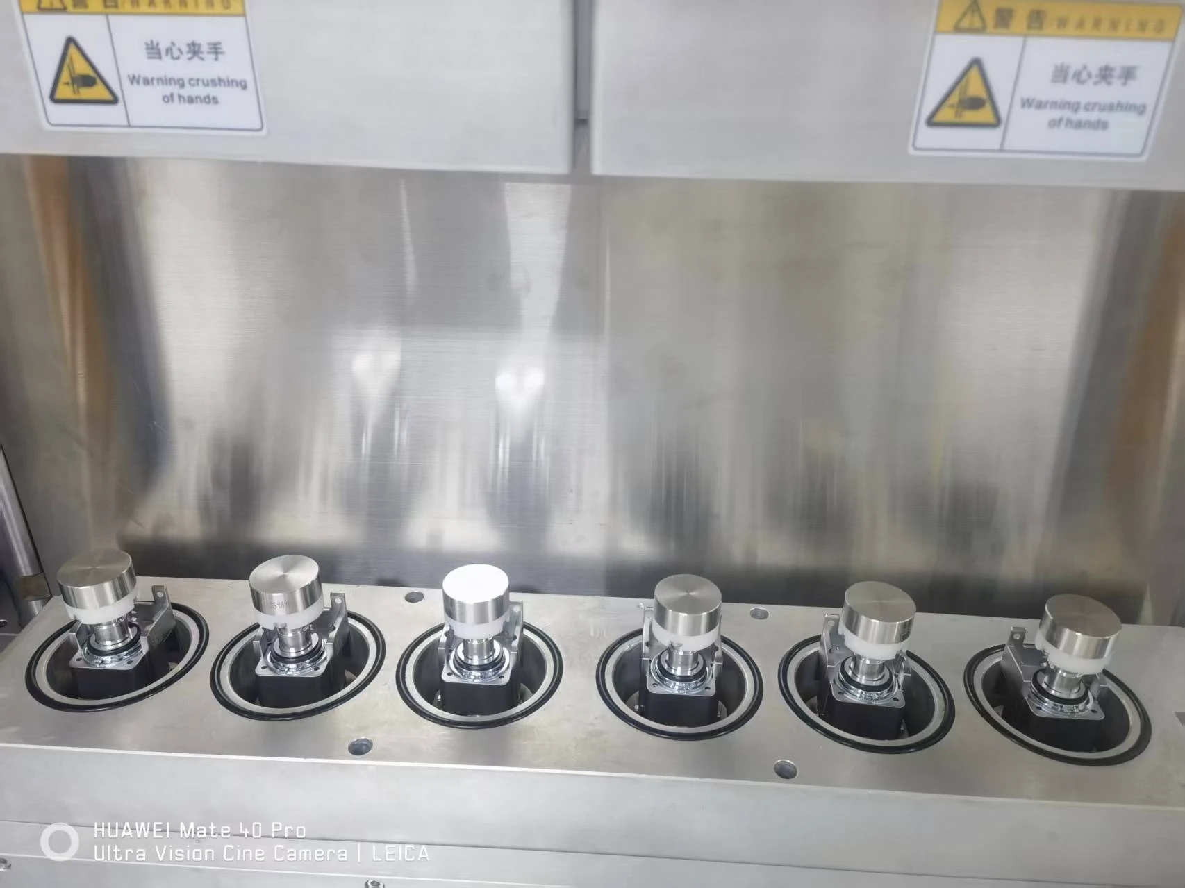
| Workpieces per chamber | 4 |
| Connector types | Male connectors, female connectors, and complete connector assemblies, using interchangeable tooling |
| Maximum workpiece dimensions | Ø33 × 88 mm |
| Maximum workpiece internal volume | 0.1 L |
| Helium filling pressure | 0–1.0 MPa, adjustable; reference setting 0.4 MPa |
| Chamber pressure at detector start | ≤30 Pa |
| Workpiece evacuation pressure | ≤2,000 Pa; pressure setting may be increased |
| Helium recovery rate | 98% for the reference configuration |
| Chamber dimensions | Confirmed for the actual connector dimensions and fixture arrangement |
Cycle Time and Batch Results
| Single chamber cycle | 80 s/chamber |
|---|---|
| Alternating dual-chamber output | 40 s per 4-piece batch; equivalent to 10 s/workpiece |
| Cycle time conditions | Reference figures apply to passing workpieces and exclude manual loading and unloading. Confirm the production cycle for the actual connector and fixture layout. |
| Batch pass/fail | An NG result identifies a failed batch. The system does not identify the individual leaking workpiece within the batch. |
Automation and Traceability
| Controls | PLC and touchscreen with password-protected settings and saved recipes for different connector types |
|---|---|
| Production display | Real-time leak rate, pass/fail results, fault diagnostics, shift test counts, and pass rate |
| Data integration | Fixed barcode scanner and industrial computer for data storage and MES integration |
| Helium management | Automatic helium recovery, pressure and concentration monitoring, replenishment, and nitrogen purging of residual helium |
| Calibration and safety | Daily chamber verification, safety light curtains, interlocks, alarms, and emergency stop |
Workpiece and Installation Requirements
| Sealing surfaces | Smooth and free of burrs, chips, welding slag, oil, and water; sealing-face roughness ≤1.6 μm and workpiece geometric tolerance ±0.1 mm |
|---|---|
| Tooling changeover | Replace the in-chamber locating and sealing tooling to test male connectors, female connectors, or complete assemblies. |
| Power and compressed air | 3 × 380 V, 50 Hz, 15 kW; dry, clean compressed air at 0.4–0.6 MPa |
| Process gases | Helium purity ≥99%; nitrogen purity ≥99% for background purging |
| Equipment illustrations | The rendering and fixture photograph show reference equipment. The specified configuration tests 4 workpieces per chamber; the final fixture layout is confirmed for the actual connector. |
Detection Process
How the Connector Leak Test Runs
Load the connectors into the locating fixtures. The automatic sequence checks for gross leaks before helium fine leak testing, then recovers helium and displays the batch result.
- 1
Load and Seal
Manually place the connectors in the locating tooling. Start the cycle to seal the workpieces automatically and close the chamber.
- 2
Check for Gross Leaks
Pre-evacuate the chamber and perform a pressure-hold check. A gross leak triggers an audible and visual alarm before the fine leak test.
- 3
Measure Helium Leakage
Evacuate the chamber and workpieces, measure the chamber helium background, and fill the workpieces with helium. The leak detector compensates for the recorded background and determines the batch pass/fail result.
- 4
Recover Helium and Unload
Recover helium for reuse, vent the chamber and workpieces, and unload the tested batch. An NG batch requires separate checks to identify the leaking connector.
Configure Your Liquid Cooling Connector Leak Test System
Share your connector drawings, male and female connector types, test pressure, target leak rate, and required throughput. We will confirm the sealing fixtures, chamber layout, and production data integration for your process.